Beobachtungen
Observations:
Vincent Reddish
Interferometrie an geometrischen Objekten, parallele Rohre
usw. /Reddish 1998/Interferometry with geometrical objects,
parallel tubes etc.
Aus den Forschungsarbeiten von V.C. Reddish ist mittlerweile die Dowsing Physics Group in Edinburgh entstanden.
weitere Publicationen siehe Reddish, The physics of dowsing, Livingston, (2003) ?????
/Jennison 1995/
From the research work of V.C. Reddish
developed meanwhile the Dowsing Physics Group in
Edinburgh.
Further publications see ....
Further publications see ....
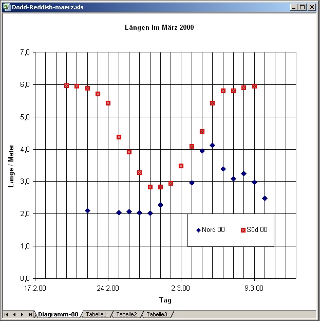
Bei den Daten der drei Jahre 1998 bis 2000 handelt es sich um den zeitlichen Verlauf einer mit einem "Interferometer" ermittelten speziellen Länge.
Es sind periodische Wechsel zu erkennen, die etwa dem Jahreszeitenwechsel Sommer und Winter entsprechen.
Die Daten für die Nord- und die Südhalbkugel verhalten sich komplementär.
Auf der Nordhalbkugel ist die Länge in der Zeit vom 25. April bis 20. November etwa 6 Meter, in der übrigen Zeit rund 2 Meter.
Die Aufteilung ist nicht 6 plus 6 Monate, sondern 7 plus 5 Monate. (in Tagen gerechnet sind das: 210 zu 155)
The data of the years 1998 to 2000 represent
the time dependence of a specific length detected with
an "interferometer".
Periodic changes are to be recognized, which correspond for instance to the season change summers and winters. The data for the north and the southern hemisphere behave complementary. In the northern hemisphere the length is in the time of 25 April until 20 November about 6 meters, in the remaining time of approximately 2 meters.
The partition is not 6 plus 6 months, but 7 plus 5 months. (i.e. counted in days: 210 to 155)
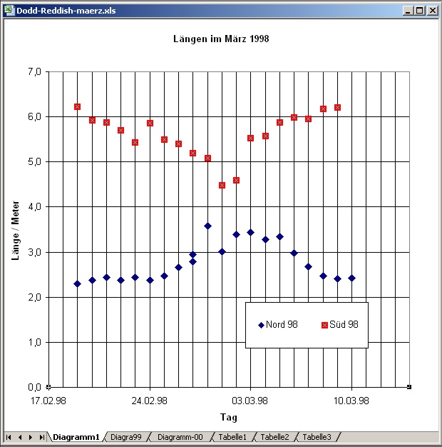
Eine kurzzeitige,
vorübergehende Zustandsänderung von etwa 5 Tagen fand
jeweil in den ersten Märztagen statt.Periodic changes are to be recognized, which correspond for instance to the season change summers and winters. The data for the north and the southern hemisphere behave complementary. In the northern hemisphere the length is in the time of 25 April until 20 November about 6 meters, in the remaining time of approximately 2 meters.
The partition is not 6 plus 6 months, but 7 plus 5 months. (i.e. counted in days: 210 to 155)
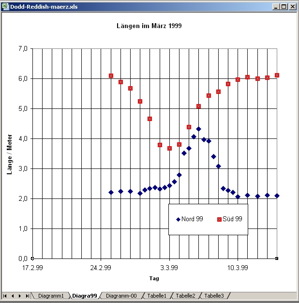
Die Änderungen sind in den drei Jahren nicht gleichartig. In 1998 ist sie etwas verwaschen, in 1999 und 2000 ausgeprägter.
A short pleliminary change
took place within about 5 days in each case in the first
March days.
The changes are not similar. In 1998 the change is smooth, in 1999 and 2000 more distinct.
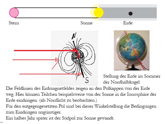
Das Verhalten würde
dem einer Eclipse (Sonnenfinsternis) entsprechen.The changes are not similar. In 1998 the change is smooth, in 1999 and 2000 more distinct.
Dies könnte ein Hinweis sein, daß es eine "Strahlquelle" geben muß, die im März kurzzeitig durch die Sonne verdeckt wurde.
Diese Quelle müßte im Sternbild Wassermann positioniert sein. dark-matter-radiation /Volkamer 2003/ ????
The
behavior would correspond to that of an eclipse (solar
eclipse).
It could be a hint for the existance of a "radiation source" which in March is covered for a short time.
This source would have to be positioned in the constellation Aquarius. dark-matter-radiation /Volkamer 2003/ ????
It could be a hint for the existance of a "radiation source" which in March is covered for a short time.
This source would have to be positioned in the constellation Aquarius. dark-matter-radiation /Volkamer 2003/ ????
Die Geografische Lage von Edinburgh ist 5 Grad West und 55,57 Grad Nord, geographic position
die von Wellington in Neuseeland 5 Grad West von 180 Grad und 41,17 Grad Süd
Die beiden Standorte liegen bezüglich der Längengrade genau gegenüber, also 180 Längengrade weiter.
Both locations are opposit to each other in
respect to their longitude.
/Reddish 1998/
«
Various hand-held devices are used as detectors in dowsing. If the reader is tempted at this point to dismiss their use as inevitably too subjective, three matters should be borne in mind.
Firstly, in order to replace the subjective detector systems currently in use by one that eliminates the human element from the detection process, and that is one of the primary objectives of present research, it may be necessary to discover the nature of the field involved in dowsing. It is unlikely that this can be done without using the presently available detectors.
Secondly, it should not be forgotten that much valuable astronomy and astrophysics was carried out in the last two centuries and the first half of this using a very subjective detector system - the eye. The scientific community did not wait for the development of photographic and photoelectric detectors before seeking to understand the nature of the Universe.
Thirdly, every detector has a sensitivity threshold. For a stimulus above the threshold, the question arises as to whether the detector just detects its presence, or does more than that and measures its strength; and in the latter case how accurate is the measurement. The design and the analysis of results of experiments must take into account the limitations of the detectors. This is a common situation in experimental physics and it applies, neither more nor less, to dowsing interferometry. »
Zur Konstruktion des "Interferometers" construction of the interferometer
/Dowsing physics group 1998/
«
CPDI . Compact Portable Dowsing Interferometer.
COMPONENTS.
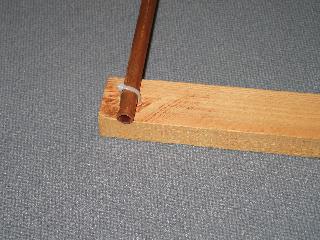
. -. Twin copper tubes; diameter 15mm. . . . . length .. (each) 1m.
4 plastic pipe clips; we use the horseshoe type with a single central screw. The pipes are pushed into them from above;
viz : U
2 wooden battens; each 33mm X 33mm X 64cm approximately.
The sections may differ from these by several mms but the battens should be a pair. The lengths may be one or two cm greater.
CONSTRUCTION.
Two pipe clips are screwed to one face of each batten, 60cm +/- 1mm apart, mounted so that pipes pushed into them are at right angles to the length of the battens. The battens must be matched so that they are both the same thickness measured from the faces to which the clips are screwed.
ASSEMBLY.
The pipes are pushed into the clips to form a rectangle in which the two pipes form the long sides 60cm apart.
NB. At these dimensions, the pattern produced by the interferometer depends more critically on'the accuracy with which
the pipes are parallel and in the same plane, than on their exact separation. That is the reason for choosing a parallelogram type of structure.
USE.
The CPDI is laid flat on level ground or on the floor, battens down. Measurements of dowsing detector rod rotations are made along a line at right angles to the copper pipes; the zero point of the line is the mid point of the rectangle. Otherwise measurement procedures are as given for Type 1. Pipes of different material may be used for particular experiments.
CAUTIONS.
1. Generally, the TU Mode of detection is implied and should be used unless the TR Mode is explicitly stated.
2. The design of the Type 1 Interferometer was discovered by inadvertently carrying a small pencil transversely in the teeth
instead of, as had been usual, above the ear, pointing forwards. This should be sufficient warning of the possible effects of
carrying small objects that may act as moving secondary components. For example, a wedding ring (gold is in the same class of dowsing materials as aluminium and tin) has been found to change completely the pattern produced by a CPDI made of twin copper pipes. Such discoveries of course provide valuable information in seeking to understand the nature of the dowsing field and the .i-n -t eraction of various materials and structures with it, understanding that may contribute towards the development of an inanimate detector system; but the apparent simplicity of the detectors and interferometers being used in research in dowsing physics should not mislead experimenters into thinking that the research is any less difficult than in other branches of experimental physics, or requires less skill and care and knowledge of the subject. »
CPDI . Compact Portable Dowsing Interferometer.
COMPONENTS.
. -. Twin copper tubes; diameter 15mm. . . . . length .. (each) 1m.
4 plastic pipe clips; we use the horseshoe type with a single central screw. The pipes are pushed into them from above;
viz : U
2 wooden battens; each 33mm X 33mm X 64cm approximately.
The sections may differ from these by several mms but the battens should be a pair. The lengths may be one or two cm greater.
CONSTRUCTION.
Two pipe clips are screwed to one face of each batten, 60cm +/- 1mm apart, mounted so that pipes pushed into them are at right angles to the length of the battens. The battens must be matched so that they are both the same thickness measured from the faces to which the clips are screwed.
ASSEMBLY.
The pipes are pushed into the clips to form a rectangle in which the two pipes form the long sides 60cm apart.
NB. At these dimensions, the pattern produced by the interferometer depends more critically on'the accuracy with which
the pipes are parallel and in the same plane, than on their exact separation. That is the reason for choosing a parallelogram type of structure.
USE.
The CPDI is laid flat on level ground or on the floor, battens down. Measurements of dowsing detector rod rotations are made along a line at right angles to the copper pipes; the zero point of the line is the mid point of the rectangle. Otherwise measurement procedures are as given for Type 1. Pipes of different material may be used for particular experiments.
CAUTIONS.
1. Generally, the TU Mode of detection is implied and should be used unless the TR Mode is explicitly stated.
2. The design of the Type 1 Interferometer was discovered by inadvertently carrying a small pencil transversely in the teeth
instead of, as had been usual, above the ear, pointing forwards. This should be sufficient warning of the possible effects of
carrying small objects that may act as moving secondary components. For example, a wedding ring (gold is in the same class of dowsing materials as aluminium and tin) has been found to change completely the pattern produced by a CPDI made of twin copper pipes. Such discoveries of course provide valuable information in seeking to understand the nature of the dowsing field and the .i-n -t eraction of various materials and structures with it, understanding that may contribute towards the development of an inanimate detector system; but the apparent simplicity of the detectors and interferometers being used in research in dowsing physics should not mislead experimenters into thinking that the research is any less difficult than in other branches of experimental physics, or requires less skill and care and knowledge of the subject. »
 |
 |
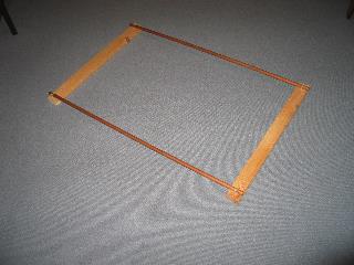
| Abb. 01a: Das
Interferometer, Nachbau, Interferometer, Reproduction. . . (FB) |
Abb. 01b: besteht aus
Holz und Kupferrohr Abstand der Rohre 60 cm. . . is made of wood and copper tube, distance of the tubes: 60 cm (FB) |
 |
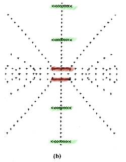 |
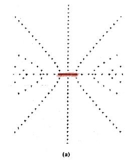
| Abb. 02a: Interferenzmuster eines einfachen Rohres (rot), jedes kleine Kreuz steht für eine Position mit spürbar größerer Intensität (Rutenreaktion) "Representational plan view showing the loci of the fringes from (a) of a single tube and (b) a pair of parallel tubes (shown as solid lines) laid on the ground. The parallel fringes discussed in this paper are shown by crosses, the scale of the figures applies to the period November to April for tube 1 m in length at Edinburgh." /Dodd 2002/ |
Abb. 02b:
Interferenzmuster von zwei parallelen Kupferrohren
(rot). Das Muster besteht aus parallelen Linien (grün), die zu den Rohren parallel sind und "radial-symmetrischen" Figuren, die -wie bei einem Scheinwerfer- von den beiden Enden der Rohre ausgehen. nach /Dodd 2002/ |
 |
|
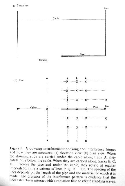
| Abb. 03: Kabel und Rohr übereinander erzeugen
Interferenzmuster. Reproduced by permission of the Royal Society of Edinburgh from Transactions of the Royal Society of Edinburgh: Earth Sciences Vol 89, (1998), pp1-9 /Reddisch 1998/ |
|
 |
|
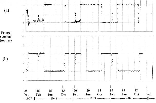
| Abb. 04: Das in Abb. 02 skizzierte
Interferenzmuster ober- und unterhalb der beiden
Objekte hat einen konstanten Linienabstand, der sich
allerdings im Laufe des Jahres sprunghaft ändert. Vergleichende Messung in Schottland (oben) und Neuseeland (unten) in der Zeit von 1997 bis 2000. Reproduced by permission of the Royal Society of Edinburgh from Transactions of the Royal Society of Edinburgh: Earth Sciences Vol 93, (2002), pp 95-99 /Dodd 2002/ "Fig. 2: Dowsing interferometer fringe spacings in the northern (a) and southern (b) hemispheres (Scotland and New Zealand) from 1997 to 2001; remarkably the patterns are inverted with respect to each other; note the sudden changes in fringe spacing in November and in April, the increasing amplitude of the isolated event in early March, and the stability at the levels of 2m and 6 m between these events." |
|
 |
|
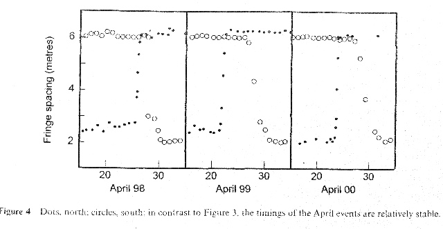
| Abb. 05a: Verlauf der Wechsel in den
April-Monaten 1998 - 2000, Schottland und
Neuseeland. Es gibt eine zeitliche Verschiebung von einigen Tagen zwischen Nord- und Südhalbkugel. Reproduced by permission of the Royal Society of Edinburgh from Transactions of the Royal Society of Edinburgh: Earth Sciences Vol 93, (2002), pp 95-99 /Dodd 2002/ "Fig. 4: Dots, north; circles, south, in contrast to Figure 3, the timings of the April events are relatively stable." |
|
 |
|
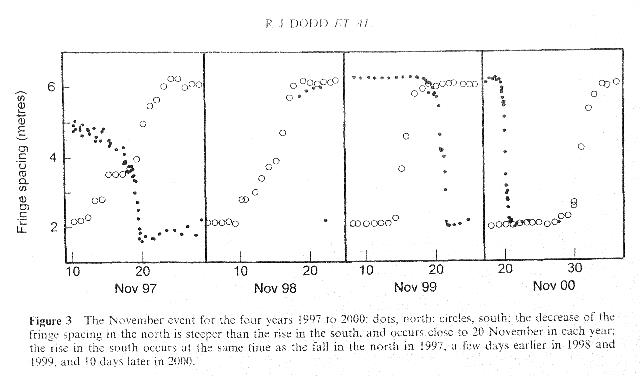
| Abb. 05b: Verlauf der Wechsel in den
November-Monaten 1998 - 2000, Schottland und
Neuseeland. Es gibt eine zeitliche Verschiebung von einigen Tagen zwischen Nord- und Südhalbkugel. Reproduced by permission of the Royal Society of Edinburgh from Transactions of the Royal Society of Edinburgh: Earth Sciences Vol 93, (2002), pp 95-99 /Dodd 2002/ "Fig 3: The November event for the four years 1997 to 2000; dots, north; circles, south; the decrease of the fringe spacing in the north is steeper than the rise in the south, and occurs close to 20 November in each year; the rise in the south occurs at the same time as the fall in the north in 1997, a few days earlier in 1998 and 1999, and 10 days later in 2000." |
|
 |
|
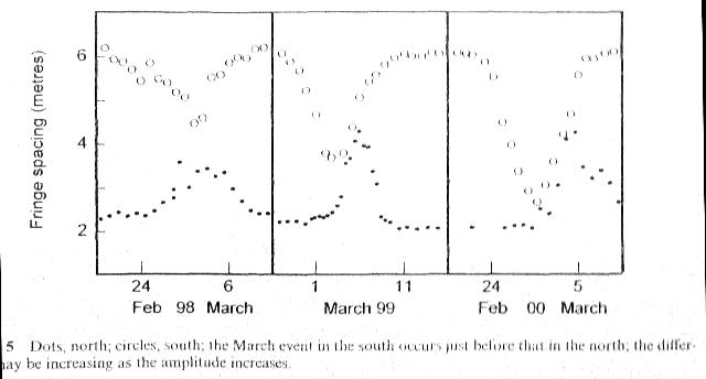
| Abb. 06: Verlauf der Wechsel in den
März-Monaten 1998 - 2000, Schottland und Neuseeland. Die Wechsel sind nur vorübergehend. Reproduced by permission of the Royal Society of Edinburgh from Transactions of the Royal Society of Edinburgh: Earth Sciences Vol 93, (2002), pp 95-99 /Dodd 2002/ "Fig. 5: Dots, north; circles, south; the March event in the south occurs just before that in the north, the difference may be increasing as the amplitude increases." |
|
 |
|
 |
|
 |
|
| Abb. 07a bis 07c: (die aus Abb. 06 entnommenen Daten von Dodd in anderer Darstellung) Lage der Schwerpunkte (Nr. des Tages) und Halbwertsbreite für die Jahre 1998 bis 2000: Nord: 03.03.98 (62) Süd: 01.03.98 (60) Nord 6 und Süd 9 Tage Nord: 06.03.99 (65) Süd: 03.03.99 (62) Nord 4 und Süd 5 Tage Nord: 05.03.00 (65) Süd: 29.02.00 (60) Nord 5 und Süd 7 Tage Position of the center (no. of days) and half-power width with the years 1998 to 2000 (FB) |
|
 |
|
| Abb. 08: Vermutung (FB): 1. Die vorübergehenden Änderungen im März könnten durch eine "Sternenfinsternis" mit Abschattung durch die Sonne zustande kommen. 2. Für die "Halbjahres"-Änderungen wäre die Neigung der Erdachse in Richtung der Sonne verantwortlich. Die Überlagerung der Wirkung von beiden Himmelskörpern, Stern und Sonne, könnte für die unsymmetrische Aufteilung mit (7+5) Monaten sorgen. Aus beiden Aussagen könnte folgen, daß es sich um die Auswirkungen eines Teilchenstroms ("Sonnenwind" ) handelt. Speculation (FB): 1. The preliminary changes in March could be generated by an eclipse of a "star" by the sun. 2. The half-year changes could be due to the inclination of the earth's axis in respect to the earth's movement around the sun. The superposition of the two bodies star and sun could affect the asymmetrical segmentation with 5 and 7 month. From both arguments it could be derived that the effect is correlated with a particle stream ("solar wind"). (FB) |
|
Versuch von V. Reddish, die Verhältnisse und Beobachtungen mit Labormitteln nachzustellen.
Attempt of V. Reddish to simulate the conditions and observations in an laboratory.
/Reddish 2010/ Cover
Vincent Reddish, sein Leben his life
«Vincent Reddish was born on 28th April 1926.
He left school at fifteen and worked in a brewery, a bank, and served in the Royal Navy before a further education grant enabled him to obtain London University honours degrees in general science and then in physics through studies at the Wigan and District Mining and Technology College. Two years research in astronomy at University College London gave him a Ph.D., and he was appointed as Lecturer in Astronomy at Edinburgh University. Five years there were followed by three doing radio astronomy at Jodrell Bank, and then appointment as Principal Scientific Officer at the Royal Observatory, Edinburgh. Author of over a hundred research papers in scientific journals, he was awarded a Doctorate of Science by the Senate of London University for research at the highest international level.
Promoted to Senior Principal Scientific Officer and then to Deputy Chief Scientific Officer, in 1975 he was appointed Director of the Royal Observatory at Edinburgh, Regius Professor of Astronomy in the University, and Astronomer Royal for Scotland. In 1980 he left to develop his own business in the tourist industry in the Central Highlands; it was there that he first saw dowsing carried out, and began the research that led to the fascinating insights recorded in this book»
/Reddish 2010/ S. 21
Reaktion des Rutengängers hängt vom Licht ab The dowsers reaction depends on the intensity of light.
«While measuring the interferometer pattern produced by the first interferometer in a pasture near Loch Rannoch one bright sunny evening, the sun set behind a local hill; it was still light but the pasture was no longer sunlit, yet the dowsing response disappeared instantly. I continued to walk back and forth along the usual track and after several minutes the pattern reappeared.
I thought no more about it until some years later when C. M. Humphries told me he had found that dowsing did not work without light and reminded me that another of our colleagues N. Duffy had reported some years ago that light had an effect on dowsing. These reminded me of the sunny evening by Loch Rannoch and led me to carry out experiments in the shielded laboratory to find outwhat effect light may have on the field produced by rotating masses.
The results were as follows.
Light is not needed for a rotating mass to generate a field. The generator can be put in a light proof cardboard box and still gives a dowsing response. Light is needed, however, on the ground where the dowser detects the field, and the strength of the detector response is proportional to the brightness of the illumination.»
/Reddish 2010/ S. 2
Haltung des Daumens und Material der L-Rute
«Figure 1 The standard L-shaped dowsing rod made of galvanised fencing wire-usually 2mm or 3mm in diameter. The way it is held with the thumb up is of importance and is standard practice within the Dowsing Physics Group; if the rod is held with the thumb round, a different set of interference fringes is detected.»
Man verwendet für die
Standard L-Rute einen galvanisierten (verzinkten)
Zaun-Draht von 2 oder 3 mm Durchmesser.
Beim Halten ist es wichtig, daß der Daumen nach oben zeigt. Wird der Daumen nach unten gebogen, findet man einen anderen Satz von Interferenz-Mustern.
Beim Halten ist es wichtig, daß der Daumen nach oben zeigt. Wird der Daumen nach unten gebogen, findet man einen anderen Satz von Interferenz-Mustern.
Das von Reddish vermuteten Modell mit zwei rotierenden Strahlquellen, Sonne und Erde, sollten in einem Laborexperiment überprüft werden. Hierzu hat er zwei elektrische Schleifmaschinen aus einem Bau-Markt als "Generatoren" verwendet. Denn, wie er herausgefunden hat, erzeugen die rotierenden Schleifscheiben ein spürbares Feld.
Um den Einfluß von Sonne und Erde auszuschalten, benutzte Reddish sowohl Aluminium als auch gereckte Polyaethylen-Haushaltfolie ("Clingfilm"). Diese Kunststoff-Folie wirkt als Polarisator und kann daher in gekreuzter Anordnung zur Abschirmung genutzt werden. Zur Abschirmung des "Erdfeldes" eignet sie sich nicht, jedoch zur Abschirmung des "Sonnenfeldes" und des der "Generatoren".
Es gibt unterschiedliches Abschirmverhalten. Wickelt man die Scheiben mit Kunststoff-Folie ein und läßt sie rotieren, dann findet man außen ein spürbares Feld, nimmt man Aluminium-Folie, dann gibt es kein Feld.
/Reddish 2010/ Seite XV
Abschirmung mit Haushaltsfolie, jedoch wenn sich die Folie mit den Scheiben mitdreht, ist sie als Abschirmung unwirksam.
Es gibt einen Unterschied zwischen der Strahlung der Sonne (solar field) und der Erde (earth's field)
« In the course of creating a shielded laboratory, described in detail in Chapter 2, further discoveries were made relating to the polarisation by stretched polyethylene film, a least two of them being of wider interest.
Firstly, each batch of film was tested as above to ensure that it polarised; not all did.
Secondly, it was found that although the crossed polarising films effectively blocked the field produced by a rotating mass when they were placed between the rotating mass and the dowser, they did not block the field if they were wrapped round the mass and rotated with it.
So although they block the solar field they are not expected to block the earth's field.»
/Reddish 2010/ Seite 11
Aluminium schirmt alles ab, auch wenn es sich mit der Scheibe mitdreht.
«The experiment was repeated using aluminium foil instead of crossed films. It made no difference whether the foil was wrapped round the protecting steel cowl or round the rotating disc; in either case the dowsing response did not appear when the generators were switched on. It is concluded that aluminium foil blocks all fields produced by rotating masses, those of the earth as well as those of the sun.»
/Reddish 2010/ Seite XV
Kommen die der Erde zugeschriebenen Felder tatsächlich von der Erde oder sind es an der Erde gestreute Felder der Sonne?
«We cannot be sure that any field we detect coming from the earth has been produced by the earth; because we, the laboratory and our instruments are all part of the rotating mass, and it is not evident that we could detect a field produced by a rotating mass of which we are part. It could, perhaps, be the field from the sun retransmitted, scattered or reflected by the earth.»
Die von russischen Autoren vorgeschlagenen "Torsionsfelder" schließt Reddish als Erklärung für seine Effekte aus.
«Fields produced by rotating masses have recently become even more controversial as a result ofarticles published by the Russian Academy of Science under the all embracing title of torsion fields; the experiments described here using rotating masses are as different from theirs as classical physics is from quantum physics and the Russian arguments are not relevant to them.»
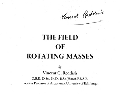 |
| Abb. 09: Titel des Buches von 2010, signiert
vom Author |
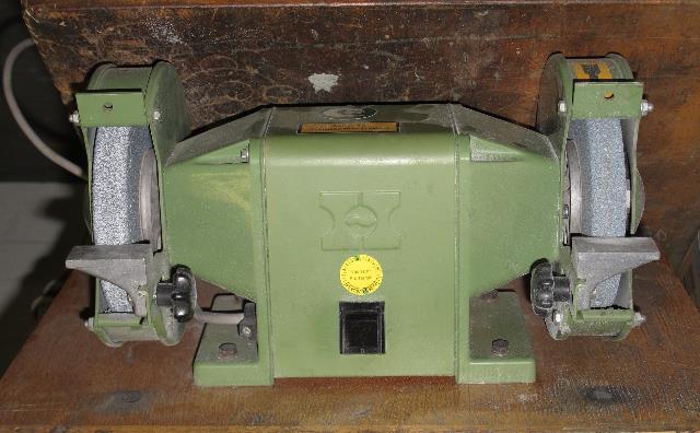 |
| Abb. 10: Maschine mit zwei Schleifscheiben.
Der Antrieb, ein Elektromotor, sitzt in der Mitte
auf der gleichen Welle. Diese Maschine erzeugt ein
spürbares Feld. Reddish nennt sie daher "Generator".
Bench grinder with two grinding wheels, the electric drive is in the middle on the same axle. As it produces a perceiveable field it is named "generator". (FB) |
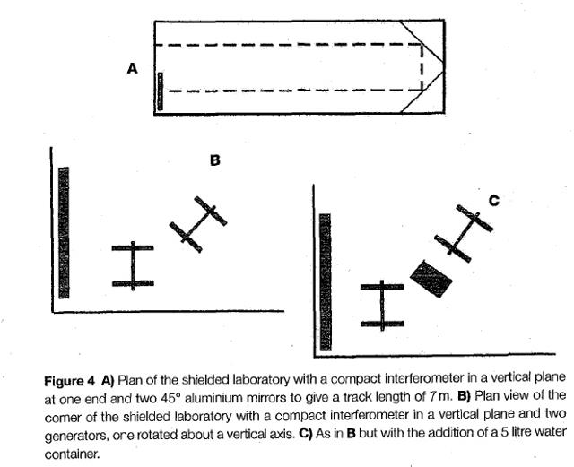 |
| Abb. 11: A: Grundriß, das abgeschirmte Labor mit einem "Kompakt Spektrometer" (wie in Abb. 01a) senkrecht an der linken Wand angebracht. Rechts sind zwei Spiegel jeweils zur Hauptrichtung angeordnet, um die Beobachtungslänge auf 7 Meter auszudehnen. B: Grundriß, zusätzlich zum Spektrometer stehen auf dem Boden zwei Schleifmaschinen (skizziert sind jeweils die beiden Scheiben und die Welle), die Drehachsen verlaufen horizontal. C: Grundriß, zwischen den beiden Schleifmaschinen befindet sich ein Behälter mit 5 Liter Wasser. /Reddish 2010/ |
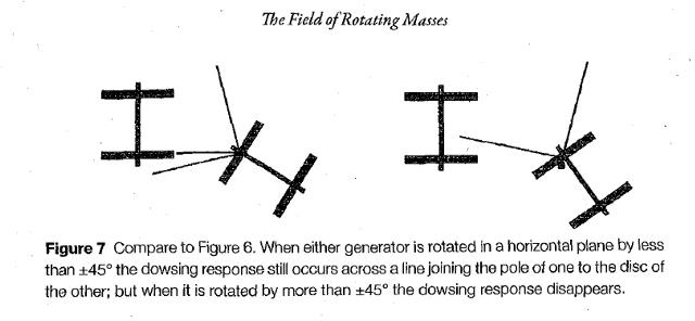 |
| Abb. 12: Bei zwei laufenden "Generatoren" gibt
es nur dann eine Rutenreaktion, sofern der Betrag
des Differenzwinkels zwischen den Achsen kleiner als
45 Grad ist. /Reddish 2010/ |
???? |
| «Figure 9 (a) A compact interferometer fixed in a vertical plane in the fully shielded laboratory, irradiated by two generators with their spin axes horizontal and parallel to the plane of the interferometer. The spin of axis one is then rotated about a vertical axis; see Figure 4b, 2000 November 4, when the fringe spacing on Figure 11 is 6m. (b) As in Figure 9a but with a 5 litre container of water placed close to the end of the spin axis of the generator being rotated; see Figure 4c. The direction of rotation is anticlockwise from 0° to 90°; 2000 Noyember 4. (c) As in Figure.9b but rotated in the reverse direction from 90°to 0°; 2000 November 2. Compare (b) and (c) with Figure 11» Messergebnisse Anfang November, als das Interferenzmuster einen Abstand von 6 m hatte. Die beiden "Generatoren" "bestrahlen" das Spektrometer an der Wand, der Raum ist nach außen vollständig abgeschirmt. Der eine Generator wird um eine senkrechte Achse schrittweise gedreht. Der andere steht mit seiner Achse fest, parallel zum Spektrometer. (b) ein fünf Liter Wasserkanister steht zwischen den Generatoren. Zum Vergleich Abb. 04. |
???? |
| «Figure 10 (a) As in Figure 9a but measured on 29 November 2000 after the fringe spacing outside (see Figure 11) had changed from 6m to 2m. :The change outside has not affected the measurements in the fully shielded laboratory. (b) As in Figure 9b with the water container in place, but measured after the November event when the fringe spacing measured outside the fully shielded laboratory has reduced from 6m to 2 m. (c) Measured in the reverse direction and with the water container in place as in Figure 9c, but after the November event when the fringe spacing measured outside the laboratory has reduced from 6m to 2 m. Compare (b) and (c) with Figure 11» Messergebnisse Ende November, als sich das Interferenzmuster auf einen Abstand von 2 m geändert hatte. |
2. Experimente 2014
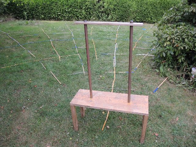 |
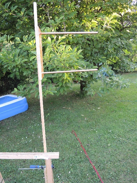
| Abb. 02-01: Zwei Kupferrohre und die
beobachteten Strukturen, Blick nach Norden Two copper tubes and the observed structures Original Date/Time: 2014-07-04T15:09:18 (FB) |
 |
| Abb. 02-02: Abstand der Kupferrohre:
43 cm, Länge 83 cm, Durchmesser 28 mm Unten stehen sie auf einem Holzzapfen, oben ist ein Kunststoff-Stopfen. Distance between the copper pipes: 43 cm, length 83 cm, diameter 28 mm. Below they stand on a wooden peg, above is a plastic plug (FB) |
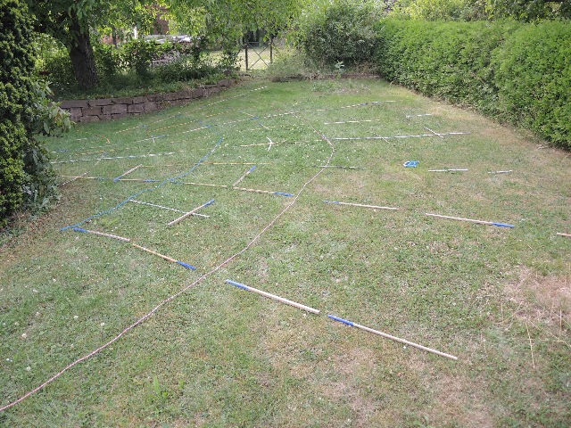 |
| Abb. 02-03: Beobachtete Strukturen Observed structures , Blick nach Nord-West
(FB) |
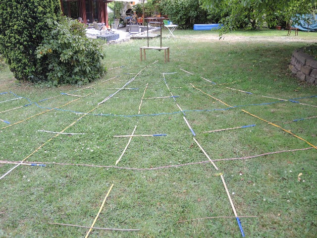 |
| Abb. 02-04: Beobachtete
Strukturen Observed
structures Blick nach Süden (FB) |
 |
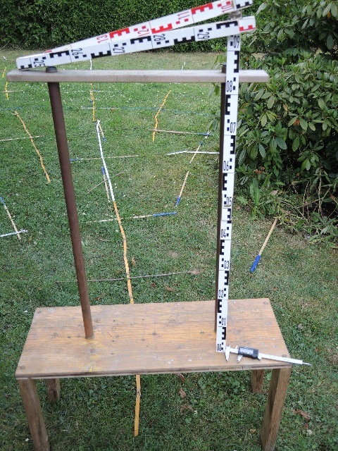
| Abb. 02-05: Aufmessung mit
2D-TRIGOTMAT-System, (zwei elektronische Maßbänder)
(FB) |
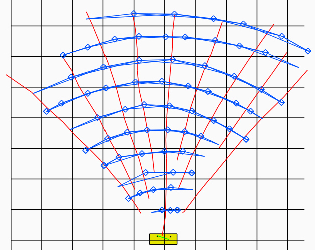 |
| Abb. 02-06: Positionen der
ausgelegten Strukturen. gelb: Tisch mit den beiden Rohren. Raster: 1m Die Rauten zeigen jeweils einen Meßpunkt an. Roh-Daten (ASCII, Texteditor): reddish0.dat Die Aufzeichnung hat laut dieser Datei weniger als acht Minuten gedauert. Die Meßgenauigkeit beträgt wenige Zentimeter. Positions of the structures laid out. yellow: table with the two tubes. Grid: 1m The diamonds show one measuring point each. Raw data (ASCII, text editor): According to this file the recording took less than eight minutes. The measurement accuracy is a few centimeters.(FB) |
 |
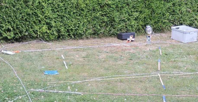
| Abb. 02-06: Kleinere Version mit 15
mm Kupferrohr, Länge 45 cm, Abstand 31 cm, Blick
nach Süden Smaller version with 15 mm copper tube, length 45 cm, distance 31 cm (FB) |
Fortsetzung reddish-zwei.htm
 |
www.biosensor-physik.de | (c)
29.03.2009 - 10.10.2025 F.Balck |
© BioSensor-Physik 2025 · Impressum